Description
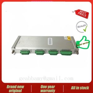
125800-01 3500/25 Electrical Current Controllers
The 125800-01 3500/25 utilises system models and real-time processes to test, validate and embedded implementations of real-time code on production task processors that can be automatically generated, as exemplified by dSPACE hardware. Due to its creation, the code is automatically optimised for fast execution and efficient use of storage. The automatic generation of code from the system model avoids errors due to manual conversion of the model code, saves time and allows software developers to concentrate on more demanding tasks.
The 125800-01 3500/25 has been modelled using the graphical display capabilities of the Simulink environment, as shown in Figure 4. The simulation model is divided into a control part and a power plant part, so that when applying dSPACE experimental validation, the control part can be executed directly in the real-time application. Using the control system model and the real-time plant, code testing, verification and embedded implementation on the dSPACE system are automatically generated. Therefore, in order to test the performance of the power line simulation, this paper develops the same a power plant using two different techniques:one using a transfer function approach and the other utilising the PLECS toolbox.
125800-01 3500/25 The tuning of the current controllers has been done using the Sisotool toolbox available in the MATLAB/Simulink environment. The analysis of the root trajectory and Bode plot of the grid current controller (PR+HC) is shown in Figure 11. The tool allows to manually set the gain of the controller, imposing a certain bandwidth, while ensuring stability by adjusting the phase difference.The MATLAB/Simulink environment is an effective tool for control design, but the model switching converter is also a technical difficulty.


