_副本")
Description
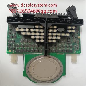
ABB EI813F 3BDH000022R1 Analogue output inverter
EI813F 3BDH000022R1 fault finding: 1, suspected analogue output board card problems, with a multimeter to measure the 4-20mA output signal, the signal is normal! 2, began to suspect that the inverter control signal input has a problem, changed a same type of inverter, it is still the case. 3, with a hand-held signal transmitter as a 4-20mA output signal source, the output signal to the frequency converter, this time the frequency converter started, rule out analogue output board and frequency converter failure.

EI813F 3BDH000022R1 is caused by the interference signal from the inverter to the analogue channel, in order to verify this, a signal isolation module TA3012 is added to the analogue 4-20mA output channel, the input terminals 5 and 6 of TA3012 are connected to the analogue output module, the output terminals 1 and 2 are connected to the frequency converter, and the terminals 3 and 4 are connected to the external 24VDC power supply. The inverter starts normally. 5, thus judging that the root of the problem is still caused by the inverter interfering with the analogue channel.

EI813F 3BDH000022R1 solution: I believe that many self-control engineers have encountered similar problems when debugging the system, therefore, I would like to share my own system debugging experience. In the PLC and frequency converter used at the same time in the automatic control system, should focus on the following matters:
1, PLC power supply and power system power supply (inverter power supply) are configured separately, and the PLC power supply should choose the isolation transformer;
2, the power line as far as possible separate from the signal line, the signal line should be shielded;
3, whether analogue signal input or analogue signal output, analogue channel always use signal isolation module;
4, PLC programme to do software filtering design;
5, signal ground and power ground separate design.