Description
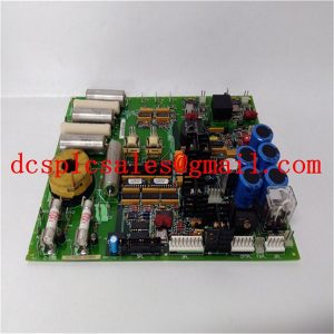
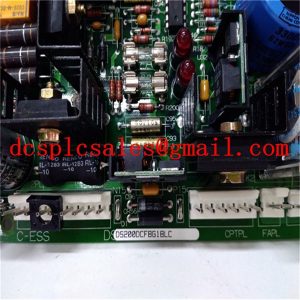
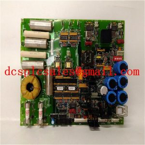
DS200TBQCG1AAA High-Speed Measurement Module
DS200TBQCG1AAA is an architecture based on PCI (Peripheral Component Interconnect) and CompactPCI plus some PXI-specific signals.PXI inherits the electrical signals of PCI, which enables PXI to have a very high data transfer capacity like PCI bus. Therefore, PXI has the ability to transfer data as high as 132Mbyte/s to 528Mbyte/s, and it is fully compatible with the software. On the other hand, PXI uses the same mechanical form factor as CompactPCI, and therefore enjoys the same characteristics of high density, rugged housing and high performance connectors.
The DS200TBQCG1AAA system consists of several components, including a chassis, a PXI backplane, a system controller module, and several peripheral modules. Here we take an eight-slot PXI system with a height of 3U as an example, as shown in Figure II. The system controller, also known as the CPU module, is located in the first slot on the left side of the chassis, with three expansion slots reserved for the system controller to allow the insertion of larger system cards due to complex functionality. The second to eighth slots are called peripheral slots, which allow users to plug in different instrument modules according to their needs.
The DS200TBQCG1AAA defines the local buses and the left and right peripheral slots connecting them to their neighbours. There are 13 left or right local buses each, and this bus allows the transmission of analogue signals in addition to digital signals. For example, peripheral slot #3 has a left local bus that can be connected to the right local bus on peripheral slot #2, while the right local bus on peripheral slot #3 is connected to the left bus on peripheral slot #4. In contrast, the left local bus on peripheral slot #3 and the right local bus are not connected to each other on the backplane unless the instrument module plugged into peripheral slot #3 connects these two signals.


