Description
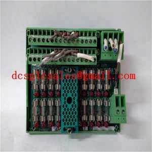
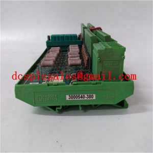
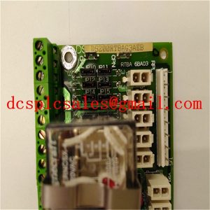
IS200TPROS1CBB IS230TSPRH1C MRP680538 Relay Control Contactors
IS200TPROS1CBB IS230TSPRH1C MRP680538 has the feature of non-sudden change of current, therefore, according to U=L*(dI/dt), it will produce an instantaneous spike voltage between the two contacts of the relay, and the amplitude of this voltage is more than the reduction of the voltage resistance of the relay’s contacts; the electromagnetic relay adopted by the relay, and the voltage resistance of the contacts is 1000V (1min). 1000V (1min)
IS200TPROS1CBB IS230TSPRH1C MRP680538 If the voltage between the contacts works for a long period of time at about 1000V, it is easy to cause the contact metal to migrate and oxidise, and the phenomenon of contact resistance becoming large, poor contact and contact bonding will occur. And the faster the frequency of action, the more serious the phenomenon. Instantaneous high voltage as shown in Figure 2, the duration of 1ms or less, the amplitude of 1KV or more. The same problem exists when the output of the transistor is an inductive load, and the instantaneous high voltage may cause damage to the transistor.
IS200TPROS1CBB IS230TSPRH1C MRP680538 An absorption protection circuit should be connected at both ends of the load when driving an inductive load. When driving DC inductive loads (such as relay coils), user circuits need to be connected in parallel with a diode (need to pay attention to the polarity of the diode); if driving AC inductive loads, user circuits need to be connected in parallel with the RC surge absorber circuit to protect the PLC’s output contacts.


